Radiographic Positioning of the Knee AP Views

This is an article for Radiologic Technologists (X-Ray Techs) about radiographic positioning of the knee in AP projections.
The knee is an important load-bearing joint in the human body. It is frequently imaged in both emergency departments as well as radiology suites. A standard examination typically includes knee AP and lateral images. Radiography of the knee may be requested to confirm or exclude fractures (to establish the presence or absence of a fracture, it should be imaged in at least two projections). Imaging of the knee is performed in trauma patients with bony tenderness, inability to bear weight, or inability to flex the knee. Radiography is also used to assess for osteoarthritis in the joint. Knee X-rays can detect joint effusions and infection.
- IR Size: 8 x 10 inches or 18 x 24 cm
- IR Orientation: Portrait
- Bucky/Grid: No
- Filter: No
- Exposure: 60 kVp and 8 mAs
- SID: 100 cm
- Shielding: Gonadal (check department guidelines)
Knee AP
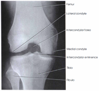
Purpose and structures shown The knee anteroposterior (AP) projection is a standard view performed to assess the knee joint and surrounding anatomy ad get a clear image of the joint spaces and soft tissues around the joint. Anatomical structures seen include the distal femur, lateral and medial epicondyles, lateral and medial femoral condyles, proximal tibia, intercondylar eminence, lateral and medial tibial plateaus, proximal fibula, head of the fibula, and patella.

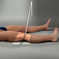
Position of patient Supine with the leg extended and the knee and ankle joint in contact with the table. Adjust the patient’s body so that the pelvis and knee are not rotated. Provide a cushion for the head. Place sandbags by the foot and ankle for stabilization, if needed.
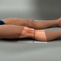
Position of part Flex the joint slightly and locate the apex of patella. Adjust the patient’s leg by placing the femoral epicondyles parallel with the IR for a true AP projection.
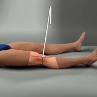
Central ray Directed to the center of the knee at a point 1.3 cm (1/2 inch) inferior to the patellar apex, parallel to the articular facets (tibial plateaus). The X-rays pass front-to-back. The minimum SID is 100 cm (40 inches).
Technical factors
- Collimation should include the distal femur superiorly, proximal tibia and fibula inferiorly, and skin margins laterally and medially. The center of the collimation field should be at the mid-knee joint space.
- The femoral and tibial condyles should be symmetrical. The femorotibial joint space should be open. The intercondylar eminence should be visualized in the center of the intercondylar fossa. This indicates no rotation.
- The fibular head should be slightly superimposed on the lateral tibial condyle. An entirely superimposed fibular head indicates rotation (in such a case, the knee should be internally rotated to bring it in even contact with the image detector).
- The patella should superimpose the distal femur in the superior part of the image and lie slightly off center to the medial side.
- Optimal exposure is indicated by visualization of the patella outline through the distal femur. The fibular head and neck should not appear overexposed. Trabecular markings should be sharply demonstrated in all bones. Soft tissue detail should be seen.
- In average sized patients, the central ray should be parallel to the articular facets (tibial plateaus). In obese patients with large thighs, the leg is naturally flexed at rest, and a slight 5-8 degree cephalic angle of the central ray may be needed. In very thin patients, a slight caudal angle of 5-8 degrees of the central ray may be required. This can be determined by measuring the distance between the ASIS and tabletop. Less than 19 cm is a slight caudal angle (thin thighs). 19 to 24 cm is a 0-degree angle (average thighs). More than 24 cm is a slight cephalad angle (thick thighs).
Knee AP Weight-Bearing Standing Bilateral
Purpose and Structures Shown The knee AP weight-bearing projection is a special view to assess the knee joint, distal femur, proximal fibula and tibia, and patella. This projection is used in orthopedics to obtain images of the bilateral knees in their natural anatomical position to assess alignment. It is used in patients with osteoarthritis to check for deformities. This view may reveal joint space narrowing which often appears normal on non-weight-bearing studies. It also allows for more accurate evaluation of the degree of varus or valgus deformity in the lower extremity. It aids in pre- and postoperative evaluation for osteotomy.

Position of patient Standing erect against an upright detector with the back toward the vertical grid device. The legs should be extended and the knee and ankle joints should be in contact with the detector. Adjust the patient’s body so that the limbs are in neutral position and the knees are not rotated.
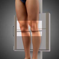
Position of part The toes should be pointing straight ahead with the feet separated enough for good balance. The patient should stand straight with the knees fully extended and the body weight equally distributed on the feet (for a unilateral weightbearing study, the entire weight should be on the imaged side with slight pressure on the toes of other side for balance). The IR should be centered at the level of the patellar apices.
Central ray Horizontal and perpendicular to center of the IR for average sized patients, entering at a point 1.5 cm below the apex of the patella. This can be determined by measuring the distance between the ASIS and tabletop. It should be between 19 and 24 cm for a 0-degree angle (i.e., central ray parallel).
Technical factors
- Collimation should be to the distal femur superiorly, proximal tibia and fibula inferiorly, and skin margins laterally and medially.
- Both knees should be demonstrated. The knee joint space should be centered in the exposure area.
- The femoral and tibial condyles should be symmetrical, indicating no rotation.
- The fibular head should be slightly superimposed on the lateral tibial condyle. An entirely superimposed fibular head indicates rotation (in such a case, the knee should be internally rotated and brought in even contact with the image detector).
- The patella should superimpose the distal femur superiorly.
- In obese patients with large thighs, the leg is naturally flexed at rest, and a slight 5-8 degree cephalic angle may be needed to better visualize the joint space (this is true when the distance between the ASIS and table is more than 24 cm). In very thin patients, a slight caudal angle of 5-8 degrees may be required (this is true when the distance between the ASIS and table is less than 19 cm).
Knee AP Oblique Lateral Rotation
Purpose and Structures Shown The knee AP oblique lateral (external) rotation provides a clear image of the medial and lateral femoral condyles, medial tibial condyle, tibial plateaus, and open knee joint.

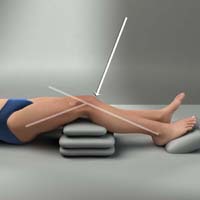
Position of patient Supine on the radiographic table with support for the ankles.
Position of part If necessary, elevate the hip on the imaged side enough to rotate the affected limb by 45 degrees laterally. Support the elevated hip and knee on the unaffected side. Center the IR 1/2 inch (1.3 cm) below the apex of the patella and parallel to the long axis of the knee. Rotate the foot so that the heel-to-toe line is 45 degrees relative to the table laterally.
Central ray Directed 1/2 inch (1.3 cm) inferior to the patellar apex. The angle is variable, depending on the measurement between ASIS and tabletop as follows: <19cm – 3 to 5 degrees caudad; 19 to 24 cm – 0 degrees; >24cm – 3 to 5 degrees cephalad.
Technical factors The medial femoral condyle and medial tibial condyle should be demonstrated. The tibial plateaus should be visible. The fibula should superimpose the lateral half of the tibia. The patellar margin should project slightly outside the edge of the femoral condyle.
Knee AP Oblique Medial Rotation
Purpose and Structures Shown The knee AP oblique medial (internal) rotation projection clearly demonstrates the femoral condyles, tibia and fibula, proximal tibiofibular joint, posterior tibia, tibial condyles, tibial plateaus, fibular head, and patella.

Position of patient Supine position with support for the ankles, if needed.
Position of part The limb is medially rotated. The foot of the affected side is inverted. The hip of the affected side is elevated enough to rotate the limb 45 degrees medially. Place a support under the hip, if needed.
Central ray Perpendicular through the knee joint 1/2 inch (1.3 cm) below the patellar apex.
Technical factors The tibia and fibula should be separate at the proximal articulation. The lateral femoral condyle and lateral tibial condyle should be demonstrated. The tibial plateaus should be visualized. patellar margin should project slightly outside the edge of the femoral condyle.
Knee AP Axial (Beclere Method)
Purpose and Structures Shown This projection best demonstrates the intercondylar fossa, posteroinferior surface of the femoral condyles, intercondylar eminence, and knee joint space. This allows evaluation for bony or cartilaginous pathology, osteochondral defects, or joint space narrowing. This is the reverse of the PA axial projection for patients who cannot assume the prone position. This projection is not preferred due to increased distance between the imaged part and the IR as well as distortion from the CR angle and increased exposure of the gonadal region.
Position of patient Supine position. Adjust the body so that it is not rotated.
Position of part Flex the affected knee by 40 to 50 degrees, enough to place the long axis of the femur at an angle of 60 degrees to the long axis of the tibia. Support the knee on sandbags. Place the IR under the knee, centered to the mid-knee joint area.
Central ray Perpendicular to the long axis of the tibia, entering the knee joint 1/2 inch (1.3 cm) below the patellar apex.
Technical factors
- The collimation field should be centered to the mid-knee joint area.
- The intercondylar fossa should be open and in profile without superimposition by the patella.
- The intercondylar eminence, tibial plateaus, and distal femoral condyles should be clearly demonstrated.
- Symmetric appearance of the distal posterior femoral condyles as well as superimposition of half the fibular head by the tibia is indicative of no rotation.
- Soft tissues in the knee joint space and visualization of the patellar outline through the femur indicate optimal exposure.
- Sharp and clear trabecular markings in the proximal tibial and femoral condyles indicate no motion.
Suggested Reading
Radiography of the leg and knee: An overview of anatomy and pathology
Radiographic positioning of the leg
Radiographic positioning of the knee in PA views
Radiographic positioning of the knee in lateral views
Radiographic positioning of the knee in patella views
RLKA
Read more about this and other subjects and get 2 Category A ARRT® CE Credits in the X-Ray CE Course “Radiography of the Leg, Knee, and Ankle”