Radiographic Positioning of the Femur and Tib Fib
This article for the Radiologic Technologist (X-Ray Tech) discusses radiographic positioning of the leg.
Femur AP
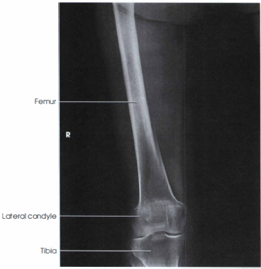
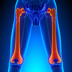
Purpose and Structures Shown Proximal femur radiograph demonstrates the majority of the shaft, pelvic brim, obturator foramen, acetabulum, ischial spine, femoral head, and femoral neck. Distal femur radiograph demonstrates the distal 2/3rd of the femoral shaft, femoral condyles and epicondyles, knee joint, and proximal tibia and fibula. Femur AP view is performed to look for evidence of pathology or injury in the femur. It may be obtained for suspicions of bony injury based on clinical signs and symptoms or if hip or knee X-rays have partially imaged a femur fracture.

Position of patient Supine position. Make sure the pelvis is not rotated by ensuring the ASIS is equidistant from the table top on either side.
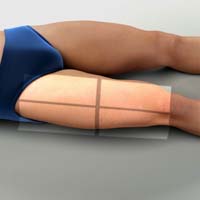
Position of part Ideally, the entire bone should be included along with the hip and knee joints. If the patient is too tall to include the entire femur, two images should be obtaned with a minimum of 2 inches (5 cm) of overlap. The size of the second IR depends on the length of the bone and coverage required; a proximal femur radiograph plus an AP knee may suffice, for exapmle. Include the joint closest to the area of interest in one image. Include the knee for a projection of the distal femur and rotate the patient’s limb internally to place it in true AP position. The epicondyles should be parallel with the IR. Include the hip for the proximal femur, include the hip joint, and place the top edge of the IR at the level of the ASIS (anterior superior iliac spine). Rotate the limb internally 10 to 15 degrees to get the femur in true AP position and place the femoral neck in profile (do not perform in patients with suspected fracture). If the femoral heads are separated by an unusually broad pelvis, the bodies (shafts) will be more strongly angled toward the midline.

Central ray Perpendicular to the mid-femur at the center of the IR.
Technical factors A properly positioned and exposed Femur AP radiograph demonstrates the following:
- The femoral neck is seen in profile.
- The greater trochanter is seen in profile laterally.
- The lesser trochanter is superimposed by the femoral neck.
- Femoral epicondyles are in profile.
- Femoral condyles are symmetrical.
- The fibular head superimposes the tibia partially (about 0.5 cm or 1/4 inch).
- Bony trabeculations are evident in the femoral shaft.
- Surrounding soft tissues are well visualized.
- On a proximal femur radiograph, if the pelvis is rotated, one side will be closer to the IR with the ischial spine superimposing the pelvic brim and a decreased obturator foramen. The other side will be further from the IR and will show the ischial spine closer to the acetabulum with an increased obturator foramen.
- Internal rotation of the foot is necessary for a true AP position of the femur. Failure to do so results in foreshortening of the femoral neck and more of the lesser trochanter being visualized (do not internally rotate in case of suspected fracture).
Femur Lateral
Purpose and Structures Shown Femur lateral view is at 90 degrees to Femur AP. It demonstrates the lateral femur and adjacent joints. If needed, use two IRs to demonstrate the entire length of an adult femur with at least 2 inch (5 cm) overlap between the two images. This position is not usually recommended for patients with fracture or patients who may have destructive disease due to the risk of fragment displacement. Patients with these conditions should be examined in the supine position.


Position of patient Ask the patient to turn onto the affected side. Adjust the body position and center the affected thigh to the midline of the grid.

Position of part Include the knee for a projection of the distal femur. Draw the patient’s uppermost limb forward and support it at the hip level on sandbags. Adjust the pelvis in true lateral position. Flex the affected knee about 45 degrees. Place a sandbag under the ankle and shift the body rotation to place the epicondyles perpendicular to the tabletop. Adjust the position of the Bucky tray so that the IR projects about 2 inches (5 cm) beyond the knee to be included. Include the hip for a projection of the proximal femur. Place the top of the IR at level of the ASIS. Draw the upper limb posteriorly and support it. Adjust the pelvis so that it is rolled posteriorly just enough to prevent superimposition; 10 to 15 degrees from the lateral position is sufficient. If shielding is used, be sure the shield doesn’t obstruct an area of clinical interest.
Central ray Perpendicular to the mid-femur and center of IR.
Technical factors In a properly obtained lateral femur projection, the following are seen:
- The femoral shaft is seen without foreshortening.
- The femoral neck is demonstrated on end.
- The greater trochanter is below the femoral neck.
- The trochanters are not prominent.
- The femur is in the center of the field.
- The majority of the femur is visualized.
- There is no superimposition by the opposite thigh.
- The femoral epicondyles are peripendicular to the IR.
- Orthopedic devices should be included in their entirety.
- The femoropatellar joint space is demonstrated.
- The patella is seen in profile.
- The fibular head is beneath the tibia.
- Presence of the greater trochanter laterally indicates not enough rotation. Presence of the greater trochanter medially indicates over-rotation. One condyle anterior to the other is indicative of under- or over-rotation.
- Trabecular markings are seen in the femoral shaft.
Video Credit : klhellens
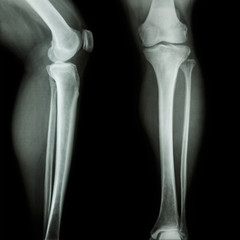
Tibia Fibula Lateral
Purpose and Structures Shown Lateral view of the entire tibia and fibula in mediolateral projection, including the knee and ankle joint. This is one of two radiographs in the tib/fib series comprising an AP and lateral view. It is performed to evaluate trauma, deformity, inflammation (osteomyelitis), foreign bodies, and inability to bear weight. The lateral projection is at 90 degrees to the AP projection. It must include the knee and ankle joints both.
Position of patient Lateral recumbent position with the lateral aspect of the knee and ankle in contact with the table so that the tibia is parallel to the table. The opposite leg should be placed behind the affected leg to avoid over-rotation.
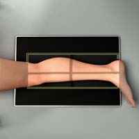
Position of part Place the patient toward the affected side with the leg on the IR. Adjust the rotation of the body to place the patella perpendicular to the IR. Use supports where needed for the patient’s comfort and to maintain the body position. Lift the leg enough for the assistant to slide a rigid support under the patient’s leg. The IR may be placed between the legs and the central ray directed from the lateral side.
Central ray Perpendicular to the IR at the mid-point of the shin, midway between the knee and ankle joints. Include the proximal and distal ends of the tibia and fibula. If the patient must remain supine due to trauma, the image may be taken cross-table using a modified horizontal beam view. In this case, the IR is placed vertically adjacent to the lateral aspect of the upright ankle. The CR is then directed horizontally at a point midway between the knee and ankle joints.
Technical factors
- Place the detector in diagonal orientation to get the entire lower limb in one image.
- The fibula is projected posterior to the tibia with superimposition at the proximal and distal end both.
- The skin margins are not cut off.
- The knee and ankle joints are both visible. Dedicated views may be performed if pathology or injury is suspected.
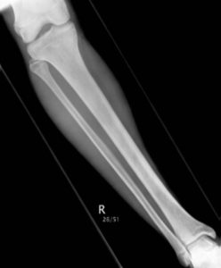
Tibia Fibula AP
Purpose and Structures Shown To view the entire tibia and fibula and demonstrate the lower limb in its natural anatomical position. This projection is at 90 degrees to the lateral view.
Tib fib AP view
Position of patient Supine on the radiographic table.
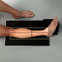
Position of part Perform oblique projections of the leg by rotating the limb 45 degrees medially or laterally. For medial rotation, ensure that the whole leg is turned inward and not just the foot. Place a support under the greater trochanter if needed.
Central ray Perpendicular to the IR at the mid-point of the shin.
Suggested Reading
Radiography of the leg and knee: An overview of anatomy and pathology
Radiographic positioning of the knee in AP views
Radiographic positioning of the knee in PA views
Radiographic positioning of the knee in lateral views
Radiographic positioning of the knee in patella views
RLKA
Read more about this and other subjects and get 2 Category A ARRT® CE Credits in the X-Ray CE Course “Radiography of the Leg, Knee, and Ankle”