Radiographic Positioning of the Knee PA Views
This article is intended for the Radiologic Technologist (X-Ray Tech). It discusses radiographic positioning of the knee in PA projections.
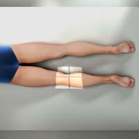
Knee PA
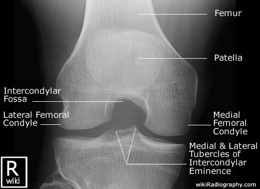
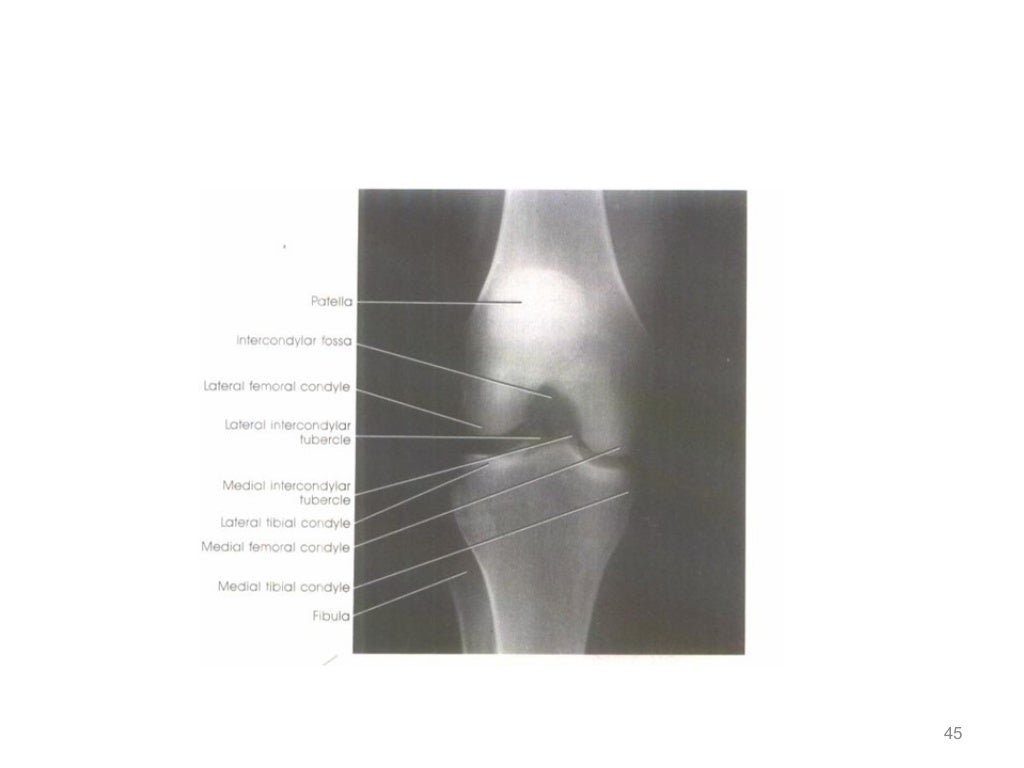
Purpose and Structures Shown To demonstrate a posteroanterior (PA) image of the knee. This provides a clear view of the open joint spaces and soft tissues around the knee joint as well as bony details surrounding the patella.

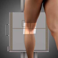
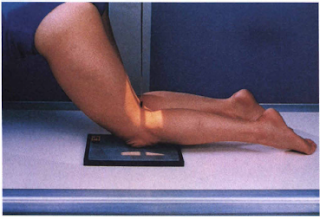
Position of patient Prone (face down) with the toes resting on the radiographic table. Sandbags may be placed under the ankles for support.
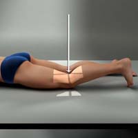
Position of part A point 1.3 cm below the patellar apex should be centered on the IR. The femoral epicondyles should be parallel with the tabletop.
Central ray Perpendicular, to exit at a point 1/2 inch (1.3 cm) inferior to the patellar apex. Since the tibia and fibula are slightly inclined, the CR will be parallel to the tibial plateau.
Knee PA Weight Bearing Standing (Rosenberg Method)
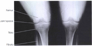
Purpose and Structures Shown To evaluate the femorotibial joint spaces and demonstrate narrowing and/or articular cartilage degeneration. These features are used to evaluate degenerative and inflammatory joint conditions such as osteoarthritis and other pathologies of the knee joint. The image is similar to that obtained when imaging the intercondylar fossa. To compare the two sides, both knees are included in the exposure.
Position of patient Standing with the anterior aspect of the knees centered to the vertical grid device. The patient should hold onto the bucky device for support and balance. The patient may need to stand on a step-stool so that the knees are placed high enough for a 10-degree caudal angle. The feet are positioned straight ahead and the body weight is distributed evenly on both sides. The knees are flexed to place the femurs at an angle of 45 degrees.
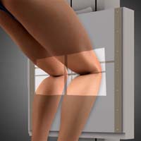
Position of part The knees are in contact with the vertical grid device. The IR is centered at a level 1 inch (1.3 cm) below the apices of the patellae.
Central ray The CR may be angled perpendicular through the knee joints. In the Rosenberg method, a 10-degree caudal angle is used with the CR centered between the knee joints at a point 1/2 inch (1.3 cm) below the patellar apices.
Technical factors
- Collimation to the bilateral knee joint region with the distal femur and proximal tibia included on each side for alignment.
- The femorotibial joint space and intercondylar fossa should be visible bilaterally.
- Symmetric appearance of the femoral and tibial condyles is indicative of no rotation.
- The intercondylar fossa should be open.
- Sharp and clear trabecular markings in all bones are indicative of no motion.
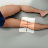
Knee PA Oblique Lateral Rotation
Purpose and Structures Shown Clear image of the medial femoral and tibial condyles, tibial plateaus, and open knee joint.
Position of patient Prone position.
Position of part Elevate the hip on the affected side. Laterally rotate the toes and knee to form a 45-degree angle. Knees should be flexed about 10 degrees.
Central ray Perpendicular and through the knee joint at a level 1/2 inch (1.3 cm) below the patellar apex.
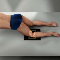
Knee PA Oblique Medial Rotation
Purpose and Structures Shown Demonstration of posterior tibia, both tibial plateaus, lateral condyles of the femur, patella, fibular head, proximal tibiofibular joint, and tibial condyles.
Position of patient Prone position.
Position of part Medially rotate the leg and foot and elevate the hip of the unaffected side to rotate the limb 45 degrees medially. Place support under the hip, if needed.
Central ray Perpendicular through the knee joint at a level 1/2 inch (1.3 cm) below the apex of the patella.
Knee PA Axial Holmblad Method
Purpose and Structures Shown This projection best demonstrates the intercondylar fossa of the femur, femoral condyles, tibial plateaus, and intercondylar eminence. It is useful in evaluating for bony or cartilaginous pathology and narrowing of the joint space.
Position of patient Keeping in mind safety, the patient can be placed in one of two positions. In both approaches, the patient leans on something for support. In the standing position, the knee is flexed and placed in contact with the front of the IR. In the kneeling position, the knee is on the table over the IR.
Position of part For both positions, the IR should be placed against the anterior surface of patient’s knee. The IR is centered to the apex of the patella. The knee is flexed 70 degrees from full extension (20 degrees difference from the CR). For the kneeling approach, the patient kneels on all fours. The IR is placed under the affected knee centered to the popliteal crease. Support should be placed under the affected ankle and leg to reduce pressure on the knee. The patient should lean forward 20-30 degrees. This will result in 60-70 degrees of knee flexion.
Central ray Perpendicular to the lower leg, entering at the midpoint of the IR for both positions.
Technical factors
- Collimation should be centered to the mid-knee joint area.
- The intercondylar fossa, tibial plateaus, and knee joint space should be clearly demonstrated.
- The patella should not superimpose the intercondylar fossa, which should appear open and in profile.
- Symmetric appearance of the distal posterior femoral condyles and superimposition of half the fibular head by the tibia is desirable and indicative of no rotation.
- Articular facets (tibial plateaus) and intercondylar eminence should be well demonstrated without any superimposition.
- Visualization of soft tissues in the knee joint space and the outline of the patella through the femur is indicative of optimal exposure.
- Clear and sharp trabecular markings in the femoral condyles and proximal tibia indicate no motion.
Knee PA Axial Camp-Coventry Method (Tunnel View)
Purpose and Structures Shown Open intercondylar fossa, posteroinferior surface of femoral condyles, medial and lateral intercondylar tubercles of intercondylar eminence, and knee joint space. An intercondylar fossa projection may be included in routine examinations of the knee joint to detect loose bodies or joint mice. The projection is also used in evaluating split and displaced cartilage in osteochondritis dissecans. Also, to identify flattening or underdevelopment of the lateral femoral condyle in congenital slipped patella.
Position of patient Prone position with a pillow under the head for support. Adjust the body so that it is not rotated.
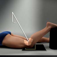
Position of part Flex the patient’s knee to either a 40- or 50-degree angle. Rest the foot and ankle on a suitable support. Center the upper half of IR to the knee joint. The CR angulation projects the joint to the center of the IR. A protractor may be used beside the leg to determine the correct leg angle. Adjust the leg so that the knee has no medial or lateral rotation.
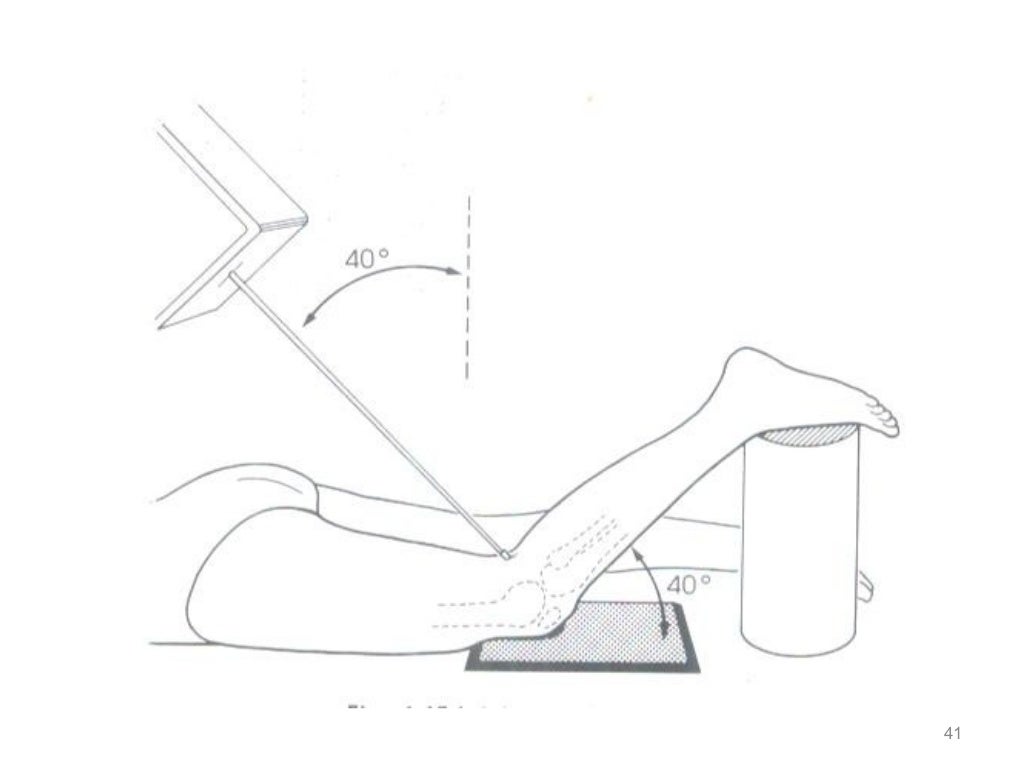
Central ray Perpendicular to the long axis of the leg and centered to the knee joint. Angled 40 degrees when the knee is flexed 40 degrees and 50 degrees when the knee is flexed 50 degrees.
Technical Factors The following anatomy is demonstrated on a properly obtained tunnel view X-ray of the knee:
- Open intercondylar fossa is visualized to enable detection of loose bodies (joint mice).
- Posteroinferior surface of the femoral condyle is seen.
- Intercondylar eminence is seen.
- Knee joint space is visualized.
- Apex of the patella does not superimpose the intercondylar fossa.
- Slight tibiofibular overlap is present, indicating no rotation.
- Interspaces and soft tissues in the fossa are demonstrated.
- Bony details are seen in the distal femur, proximal tibia, and tibial eminences.
Suggested Reading
Radiography of the leg and knee: An overview of anatomy and pathology
Radiographic positioning of the leg
Radiographic positioning of the knee in AP views
Radiographic positioning of the knee in lateral views
Radiographic positioning of the knee in patella views
RLKA
Read more about this and other subjects and get 2 Category A ARRT® CE Credits in the X-Ray CE Course “Radiography of the Leg, Knee, and Ankle”