Radiographic Positioning of the Skull
This article discusses radiographic positioning of the skull for the Radiologic Technologist (X-Ray Tech).
- Skull PA Occipito-Frontal
- Skull PA Axial Caldwell Method
- Skull PA Axial Haas Method
- Skull AP Fronto-Occipital
- Skull AP Axial Towne Method
- Skull Lateral Supine
- Skull Lateral Standing Erect
- Skull Occipitomental Waters View
- Skull Submentovertical Projection Schuller Method
- Skull Verticosubmental Projection Scholler Method
Skull Anatomy
The skull is a solid bony structure that encloses and protects the brain and other components of the central nervous system. It consists of 8 cranial bones and 14 facial bones (see our article on radiographic positioning of the face and mandible). The back of the cranium consists of the occipital and right and left parietal bones. The vertex is made up of the paired parietal bones joining the frontal bone at the sagittal suture. The right and left parietal bones and right and left temporal bones make up the sides of the cranium. The front of the cranium consists of the frontal bone. The base of the skull is complex and consists of the paired temporal bones as well as the sphenoid and ethmoid. The base has numerous foramina to allow passage of nerves, veins, and arteries. Radiologists use the images of the skull to assess the size, shape, thickness, and density of skull bones as well as vascular markings and sutures. Due to the complexity of skull anatomy, technologists require an in-depth understanding and attention to detail during radiographic imaging of the face and skull. To this end, we have separate articles, for example, radiographic positioning of the mastoid process, that provide more detailed information.
Major Landmarks in Skull Radiography
- Vertex
- External Occipital Protuberance
- External Auditory Meatus
- Outer Canthus of the Eye
- Infraorbital Point
- Glabella
- Nasion
- Acanthion
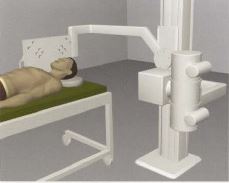
Patient Positioning for Skull Radiography
Patients can be imaged either erect or recumbent. In the erect position, a standard X-ray table and upright Bucky are used. This allows easy and quick positioning and use of a horizontal beam, which is necessary to demonstrate any air-fluid levels in the cranium or sinuses. The patient’s head needs to be positioned precisely during skull radiography, but techs should remember to keep the body in a comfortable position, using aids such as pillows and sponges if necessary. In general, respiration is suspended during exposure to prevent artifacts due to breathing movements, although this may not be possible in patients with severe trauma. RTs must remember to perform appropriate handwashing and hygiene measures as well disinfection of surfaces since radiographic positioning of the skull frequently requires direct contact between the patient’s face and the technologist’s hands and table/Bucky surface.
Imaging Planes for Skull Radiography
In order to produce accurate images and reproducing positioning, technologists must understand the planes used in skull radiography. For example, the median sagittal plane is a vertical plane perpendicular to the ground that separates the skull into equal right and left halves when viewed from the front of the patient. The coronal plane (auricular plane) is a vertical plane that divides the skull into anterior and posterior parts along the auricular line. The transverse plane (anthropological plane) is a horizontal plane that splits the skull into upper and lower halves.
Baselines Used in Skull Radiography
- The orbitomeatal line (OML) runs from the nasion through the outer canthus of the eye to the center of the external auditory meatus.
- The infraorbitomeatal line (IOML) runs from the inferior orbital margin to the upper border of the external auditory meatus.
- The meatomental line (MML) runs from the external auditory meatus to the mental point (tip of chin).
- Other lines used in skull radiography include the glabellomeatal (GML), acanthomeatal (AML), and lipsmeatal (LML).
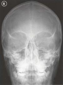
Skull PA Occipito-Frontal
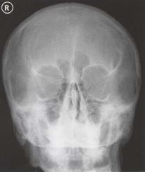
Purpose and Structures Shown To get a clear posteroanterior image of the skull and demonstrate pathology such as skull fractures with medial and lateral displacement. This projection demonstrates the frontal bone, crista galli, internal auditory canals, anterior ethmoid and frontal sinuses, greater and lesser wings of the sphenoid, and petrous ridges.
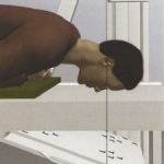
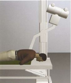
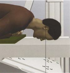
Position of patient Prone with the vertical beam angled at 20 degrees. This position should never be used if there is a possibility of facial bone fractures or in unconscious patients.
Position of part Remove dentures, hair grips, ear clips, and anything from the hair. Provide a mattress under the body for comfort. The hands should be under the chest. The forehead and nose are on the table.
Skull PA Axial Caldwell Method
Purpose and Structures Shown A caudally angled PA radiograph of the skull to visualize the frontal sinus and other paranasal sinuses. This projection demonstrates skull fractures with medial and lateral displacement. Structures shown include the greater and lesser sphenoid wings, superior orbital fissures, frontal bone, anterior ethmoid and frontal sinuses, superior orbital margins, and crista galli.
Position of patient Standing erect with the tube angled at 15 degrees caudal. The patient’s nose and forehead are placed against the IR. Keeping the orbitomeatal line perpendicular to the IR ensures no tilt or rotation. Centering is at the nasion. The midsagittal plane is perpendicular to the IR to ensure no tilt.
Position of part Remove dentures, hair grips, ear clips, and anything from the hair. The patient should be asked to suspend respiration during exposure. In a properly positioned Caldwell image, the petrous ridges are symmetric and project into the lower third of the orbits. The medial and lateral orbital margins are equidistant from the lateral cranium on either side indicating no rotation.
Skull PA Axial Haas Method
Purpose and Structures Shown A PA projection of the skull to visualize the sellar structures projecting into the foramen magnum in patients who cannot be positioned for the AP axial projection. Structures demonstrated include the occipital bone, foramen magnum, and petrous pyramids along with the posterior clinoids and dorsum sellae in the shadow of the foramen magnum.
Position of patient Prone with the central ray directed cephalad at an angle of 25 degrees. The angulation can be varied to demonstrate other anatomy as needed. The midsagittal plane is centered to the midline of the grid. The elbows are flexed and the arms are placed in a comfortable position. The shoulders are adjusted to lie flat against the table in the same horizontal plane.
Position of part Remove dentures, hair grips, ear clips, and anything from the hair. The patient’s nose and forehead rest on the table. Neck flexion is adjusted to ensure the orbitomeatal line is perpendicular. The head is immobilized. The patient should be asked to suspend respiration during exposure. The image shows the occipital region of the skull with symmetric petrous pyramids. The dorsum sellae are projected into the foramen magnum. The entire cranium is visualized with a symmetric distance between the lateral border of the skull and the lateral margin of the foramen magnum on both sides.
Video Credit : ela drozd
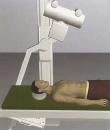
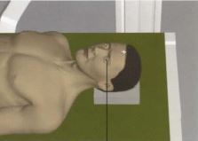
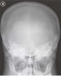
Skull AP Fronto-Occipital
Purpose and Structures Shown To get a clear anteroposterior image of the skull. Anatomy seen includes the frontal bone, crista galli, internal auditory canals, ethmoid and frontal sinuses, and greater and lesser wings of the sphenoid.
Position of patient Supine with the vertical beam angled at 20 degrees. This position is used for patients who cannot be imaged in the prone position.
Position of part Remove dentures, hair grips, ear clips, and anything from the hair. Provide a mattress under the body for comfort. The head should lie flat and raised on a thin radiolucent foam rubber pad. A pillow should NOT be used. Center between the eyes at the root of the nose.
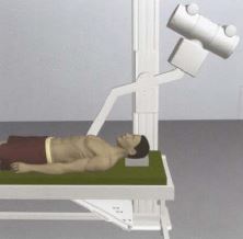
Skull AP Axial Towne Method
Purpose and Structures Shown An additional view of the occipital skull which can demonstrate skull fractures. The occipital bone, petrous pyramids, and foramen magnum are visualized. The posterior clinoids and dorsum sellae are seen in the shadow of the foramen magnum.
Position of patient Supine with the vertical beam angled at 30 degrees.
Position of part Remove dentures, hair grips, ear clips, and anything from the hair. Provide a mattress under the body for comfort. The head should lie flat and raised on a thin radiolucent foam rubber pad. A regular pillow should NOT be used. Center to the top of the head 7-8 cm from the root of the nose. The image shows the Sella turcica projected in the foramen magnum. The entire occipital bone, the posterior portion of the parietal bone, and the lambdoid suture should be clearly demonstrated. The petrous pyramids are symmetric and the distance between the lateral skull margin and lateral border of the foramen magnum is equal on either side.
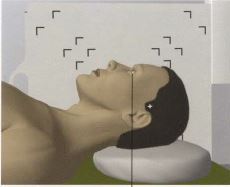
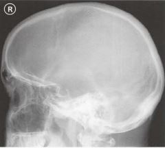
Skull Lateral Supine
Purpose and Structures Shown A right/left lateral view of the skull that demonstrates pathology such as skull fractures. A common routine skull series includes the right and left lateral. Details of the lateral cranium closest to the IR are demonstrated in the image which shows superimposed cranial halves. The sella turcica, clinoids, and dorsum sellae are visualized along with the clivus in profile.
Position of patient Supine with a horizontal beam. The side of interest is closest to the IR.
Position of part Remove dentures, hair grips, ear clips, and anything from the hair. Provide a mattress under the body for comfort. The head should lie flat and raised on a thin radiolucent foam rubber pad. A regular pillow should NOT be used. The line extending from the outer corner of the eye to the opening of the ear should be perpendicular to the table. The front and back of the skull should be visible.
Skull Lateral Standing Erect
Purpose and Structures Shown A lateral view of the skull that shows the cranial structures nearest to the IR in detail. Structures seen include the dorsum sellae, anterior and posterior clinoids, and greater and lesser wings of the sphenoid.
Position of patient Standing erect. There is no tube angle. The affected side is placed against the IR. The midsagittal plane is parallel to the IR.
Position of part Remove dentures, hair grips, ear clips, and anything from the hair. The patient should be asked to suspend respiration during exposure. A properly positioned lateral skull image demonstrates the sella turcica and clivus in profile without rotation. The external auditory canals, orbital roofs, and mandibular rami are superimposed with no tilt or rotation. The base of the skull is separate from the C-spine. All the facial bones are seen.
Skull Occipitomental Waters View
Purpose and Structures Shown An angled PA view of the skull to evaluate for sinusitis and facial fractures. The anatomy demonstrated includes the frontal and maxillary sinuses, inferior orbital rim, maxillae, zygoma, zygomatic arch (see radiographic positioning of the zygomatic arch), nasal septum, and floor of orbits.
Position of patient Standing erect, facing an upright IR, slightly gazing upwards with the head straight. The OML should be 37 degrees from the IR. This can be achieved by ensuring the MML (mentomandibular line) is perpendicular to the IR. Centering is to the acanthion.
Position of part Remove dentures, hair grips, ear clips, and anything from the hair. In a properly positioned Waters view, the petrous ridge is inferior to the maxillary sinuses. Symmetry of the coronoid processes indicates lack of rotation.
Video Credit : Vien Chunggia
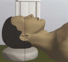
Skull Submentovertical Projection Schuller Method
Purpose and Structures Shown A radiograph of the cranial base. This projection should NOT be used in patients in whom cervical spine fracture or subluxation trauma is present or suspected. Structures shown include the foramen ovale and spinosum, the sphenoid and posterior ethmoid sinuses, mandible, hard palate, mastoid processes, petrous ridges, foramen magnum, and occipital bone.
Position of patient Supine or upright. In the upright position, a chair with a back support is recommended for comfort. The submentovertical (SMV) projection requires the infraorbitomeatal line (IOML) to be as parallel as possible to the IR. The central ray is directed perpendicular to the IOML. This can be achieved by seating the patient far enough from the grid to sufficiently hyperextend the neck. The midsagittal plane of the body is centered to the midline of the grid. In the supine position, there is considerable strain on the neck, so the final adjustment should be maintained for as short a duration as possible.
Position of part Remove dentures, hair grips, ear clips, and anything from the hair. The neck is extended as far as possible and the head rests on the vertex. A head clamp is used or adhesive tape is used across the tip of the chin and anchored to the sides of the IR. The patient should be asked to suspend respiration during exposure. A properly positioned SMV projection demonstrates symmetric petrosae, the foramina ovale, spinosum, mastoid processes, sphenoid sinuses, mandible with maxillary sinuses superimposed, and nasal septum. The atlas and dens of the axis are also visualized. The lateral margin of the skull is equidistant on both sides from the mandibular condyles.
Skull Verticosubmental Projection Scholler Method
Purpose and Structures Shown A radiograph of the cranial base obtained in patients in whom the SMV projection is contraindicated.
Position of patient Prone. The midsagittal plane is centered to the midline of the grid. The elbows are flexed and the arms are placed in a comfortable position with the shoulders flat and in the same horizontal plane. The central ray is directed perpendicular to the infraorbitomeatal line.
Position of part Remove dentures, hair grips, ear clips, and anything from the hair. The chin is extended fully. The head is immobilized. The patient should be asked to suspend respiration during exposure. The VSM projection is useful to evaluate the anterior cranial base and sphenoid sinuses. In a properly positioned VSM projection, the petrosae are symmetric and the lateral margin of the skull is equidistant on both sides from the mandibular condyles. Structures of the cranial base are visualized and the mandibular symphysis is superimposed on the anterior frontal bone.
Get 24 Category A ARRT® CE Credits in the X-Ray CE Course “Radiography of the Upper Extremities”UpEx