Radiographic Positioning of the Leg and Knee

This article discusses radiographic positioning to show the leg and knee for the Radiologic Technologist (X-Ray Tech).
Knee AP
Purpose and Structures Shown To get clear image of open joint spaces and soft tissue around the knee joint, and bony detail surrounding patella.
Position of patient Supine. Adjust body so pelvis is not rotated.
Position of part Flex joint slightly, locate apex of patella. Adjust patient’s leg by placing femoral epicondyles parallel with IR for true AP projection.
Central ray Directed to a point 1.3 cm inferior to patellar apex.
Knee PA
Purpose and Structures Shown To demonstrate PA image of knee. To get clear image of open joint spaces and soft tissue around the knee joint, and bony detail surrounding patella.
Position of patient Prone position with toes resting on radiographic table, or place sandbags under ankle for support.
Position of part Center a point 1.3 cm below patellar apex to center of IR. Femoral epicondyles parallel with tabletop.
Central ray Perpendicular to exit a point 1/2 inch (1.3 cm) inferior to patellar apex. Since tibia and fibula are slightly inclined, the CR will be parallel with the tibial plateau.
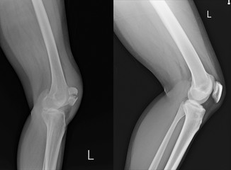
Knee Lateral Mediolateral
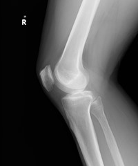
Purpose and Structures Shown To get clear image of patella in lateral profile. Structures shown are the distal end of femur, patella, knee joint, proximal ends of tibia and fibula, and adjacent soft tissue.
Position of patient Patient lying on affected side. Pelvis not rotated. Affected knee forward and extend other limb behind it.
Position of part Epicondyles perpendicular to IR. Patella will be perpendicular to plane of the IR. For new or unhealed patellar fractures; knee should usually not be flexed more than 10 degrees. Check with your medical director. Knee flexion of 20 to 30 degrees is usually preferred – this position relaxes muscles and shows maximum volume of the joint cavity.
Central ray 5 to 7 degrees cephalad at knee joint 1 inch (2.5 cm) distal to medial epicondyle. Slight angulation of CR will prevent joint space from being obscured by magnified image of medial femoral condyle.
In lateral recumbent position, medial condyle will be slightly inferior to lateral condyle.
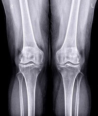
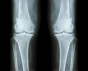
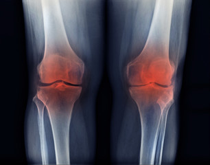
Knee AP Weight Bearing Standing Bilateral
Purpose and Structures Shown To reveal narrowing of joint space that appears normal on non-weight-bearing study. Joint spaces of knee and deformities.
Position of patient Upright position with back toward vertical grid device.
Position of part Place toes straight ahead, with feet separated enough for good balance. Ask patient to stand straight with knees fully extended and weight equally distributed on feet.
Central ray Horizontal and perpendicular to center of IR. Entering at point 1.3 cm below apices of patellae.
Knee PA Weight Bearing Standing
Purpose and Structures Shown To evaluating joint space narrowing and demonstrate articular cartilage disease. Image is similar to those obtained when radiographing intercondylar fossa.
Position of patient Standing position with anterior aspect of knees centered to vertical grid device. Holding onto something for balance, flex knees to place femurs at an angle of 45 degrees.
Position of part Knees in contact with vertical grid device. Center IR at level 1 inch (1.3 cm) below apices of patellae.
Central ray Perpendicular and through knee joints. A 10 degrees caudal angle is sometimes used.
Purpose and Structures Shown Clear image of medial femoral and tibial condyles, tibial plateaus, open knee joint.
Position of patient Supine position on radiographic table.
Position of part If necessary, elevate hip of unaffected side enough to rotate affected limb. Support elevated hip and knee of unaffected side. Center IR 1/2 inch (1.3 cm) below apex of patella. Rotate foot so that heel to toe line is 45 degrees relative to table laterally.
Central ray Directed 1 inch (1.3 cm) inferior to patellar apex. Angle is variable, depending on measurement between ASIS and tabletop, as follows: <19cm – 3 to 5 degrees caudad. 19 to 24 cm – 0 degrees. >24cm – 3 to 5 degrees cephalad.
Knee AP Oblique Medial Rotation
Purpose and Structures Shown Clear demonstration of the tibia and fibula, proximal tibiofibular joint, posterior tibia, lateral condyles of femur and tibia, tibial plateaus, and patella.
Position of patient Supine position. Support the ankles.
Position of part Limb medially rotated, hip of affected side elevated enough to rotate limb 45 degrees. Place support under hip, if needed.
Central ray Perpendicular through knee joint 1/2 inch (1.3 cm) below patellar apex.
LE-P-46 – Knee PA Oblique Lateral Rotation
Purpose and Structures Shown Clear image of medial femoral and tibial condyles, tibial plateaus, open knee joint.
Position of patient Prone position.
Position of part Elevate hip of affected side. Laterally rotate toes and knee to form a 45 degrees angle. Knees flexed about 10 degrees.
Central ray Perpendicular and through knee joint at level 1/2 inch (1.3 cm) below patellar apex.
Knee PA Oblique Medial Rotation
Purpose and Structures Shown Demonstration of posterior tibia, both tibial plateaus, lateral condyles of femur, patella, fibular head, proximal tibiofibular joint and tibial condyles.
Position of patient Prone position.
Position of part Medially rotate leg and foot, and elevate hip of unaffected side to rotate limb 45 degrees medially. Place support under hip, if needed.
Central ray Perpendicular through knee joint a level 1/2 inch (1.3 cm) below apex of patella.
Knee PA Axial Holmblad Method
Purpose and Structures Shown Clear image of intercondylar fossa of femur.
Position of patient Consider patient’s safety, Patient placed in one of 2 positions. In both approaches, patient leans on something for support. standing with knee of interest flexed and placed in contact with front of IR. kneeling on table with affected knee over IR.
Position of part For both positions, place IR against anterior surface of patient’s knee. Center IR to apex of patella. Flex the knee 70 degrees from full extension (20 degrees difference from CR).
Central ray Perpendicular to lower leg, entering midpoint of IR for both positions.
Knee PA Axial Camp-Coventry Method
 (Tunnel View)
Purpose and Structures Shown Open intercondyloid fossa, posteroinferior surface of femoral condyles, medial and lateral intercondylar tubercles of intercondylar eminence and knee joint space. In routine examinations of knee joint, an intercondylar fossa projection is usually included to detect loose bodies or joint mice. The projection is also used in evaluating split and displaced cartilage in osteochondritis dissecans and flattening, or underdevelopment, of lateral femoral condyle in congenital slipped patella.
Position of patient Prone position. Adjust body so that it is not rotated.
Position of part Flex patient’s knee to either a 40 or 50-degree angle. Rest foot on a suitable support.
Center upper half of IR to knee joint; the CR angulation projects joint to center of IR. Protractor may be used beside leg to determine correct leg angle. Adjust leg so knee has no medial or lateral rotation.
Central ray Perpendicular to long axis of leg and centered to knee joint. Angled 40 degrees when knee is flexed 40 degrees and 50 degrees when knee is flexed 50 degrees.
Knee Axial Beclere Method
Purpose and Structures Shown Open intercondylar fossa, posteroinferior surface of femoral condyles, intercondylar eminence and knee joint space.
Position of patient Supine position. Adjust body it is not rotated.
Position of part Flex affected knee enough to place long axis of femur at an angle of 60 degrees to long axis of tibia. Support knee on sandbags. Place IR under knee.
Central ray Perpendicular to long axis of tibia, entering knee joint 1/2 inch (1.3 cm) below patellar apex.
Patella PA
Purpose and Structures Shown Patella than in AP projection.
Position of patient Prone position. Place one sandbag under thigh and another under leg to relieve pressure on patella if needed.
Position of part Adjust leg to place patella parallel with plane of IR. This usually requires that the heel be rotated 5 to 10 degrees laterally.
Central ray Perpendicular to midpopliteal area exiting patella. Collimate closely to patellar area.
Patella Lateral
Purpose and Structures Shown Patella lateral profile and patellofemoral joint space.
Position of patient Lateral recumbent position.
Position of part Ask patient to turn onto affected hip. Sandbag may be placed under ankle for support.
Flex the affected knee about 5-10 degrees. Increasing flexion reduces patellofemoral joint space.
Femoral epicondyles should be perpendicular to IR.
Central ray Perpendicular to IR, entering knee at patella. Collimate closely to patellar area.
Patella PA Oblique Lateral Rotation

Purpose and Structures Shown Medial margin of patella superimposed over femur and also the lateral aspect of patella free of the femur.
Position of patient Prone position.
Position of part Flex knee 5-10 degrees. Externally (laterally) rotate knee 45 -55 degrees from prone position.
Central ray Perpendicular to IR, exiting the palpated patella.
Patella PA Oblique Medial Rotation

Purpose and Structures Shown Majority of the medial patella without the femur.
Position of patient Prone position.
Position of part Flex patient’s knee about 5-10 degrees. Medially rotate knee 45-55 degreesfrom prone position.
Central ray Perpendicular to IR, exiting palpated patella. Collimate closely to patellar area.
Patella PA Axial Oblique Kuchendorf Method


Purpose and Structures Shown Majority of patella free of superimposition by femur.
Position of patient Prone position. Elevate hip of affected side 2 or 3 inches. Place sandbag under ankle and foot. Adjust it so knee is slightly flexed (approximately 10 degrees) to relax muscles.
Position of part Laterally rotate knee about 35-40 degrees from prone position, which is more comfortable than the direct prone. Place index finger against medial border of patella, and press it laterally. Rest knee on its anteromedial side to hold patella in a position of lateral displacement.
Central ray Directed to joint space between patella and femoral condyles at an angle of 25- 30 degrees caudad.
Patella Tangential Projection Hughston Method

Purpose and Structures Shown Femoral condyles. Demonstrates subluxation of patella and patellar fractures.
Position of patient Prone position with foot resting on table.
Position of part Place IR under patient’s knee. Slowly flex affected knee so tibia and fibula form a 50- to 60 degrees angle from table. Rest foot against collimator, or support it in position.
Central ray Angled 45 degrees cephalad and directed through patellofemoral joint.
Structures shown Subluxation of patella and patellar fractures.
Patella Tangential Projection Merchant Method
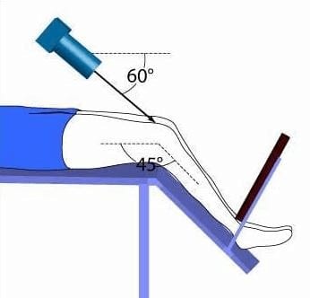
Purpose and Structures Shown Axial projection of patellae and patellofemoral joints, seen as slightly magnified images.
Position of patient Supine with both knees at end of table. Support knees and lower legs by an adjustable IR-holding device. Place pillows or foam wedge under patient’s head and back for comfort and relaxation of quadriceps femoris.
Position of part Using “axial viewer” device, raise the patient’s knees about 2 inches to place femur parallel with tabletop. Adjust angle of knee flexion to 40 degrees. Strap both legs together at calf level to control leg rotation and allow patient relaxation. Place IR perpendicular to CR and resting on patient’s shins about 1 foot distal to patellae Ensure that patient is relaxed. Relaxation of quadriceps femoris is significant for accurate diagnosis. If not relaxed, a subluxed patella may be pulled back into intercondylar sulcus, which shoes false normal appearance. Record angle of knee flexion for reproducibility during follow-up examinations.
Central ray Perpendicular to IR. With 40 degrees knee flexion, angle CR 30 degrees caudad from horizontal plane (60 degrees from vertical) to achieve a 30 degrees CR to-femur angle. CR enters midway between patellae at level of patellofemoral joint.
Patella Tangential Projection Setiegast Method (Sunrise)

Purpose and Structures Shown Vertical fractures of bone and articulating surfaces of patellofemoral articulation.
Position of patient Supine or prone, prone is preferred because knee can usually be flexed to greater degree and immobilization is easier. If patient is seated on radiographic table, hold IR securely in place.
Position of part Flex patient’s knee slowly as much as possible or until patella is perpendicular to IR if patient’s condition permits. With slow, even flexion, patient will be able to tolerate position, whereas quick, uneven flexion may cause too much pain. Loop a long strip of bandage around the patient’s ankle or foot if desired. Have patient grasp ends over shoulder to hold leg in position. Gently adjust leg so its long axis is vertical.
Central ray Perpendicular to joint space between patella and the femoral condyles when the joint is perpendicular. If not, degree of CR angulation depends on degree of flexion of knee. The angulation typically will be 15 to 20 degrees. Close collimation is recommended.
Femur AP
Purpose and Structures Shown Demonstrates femur, knee joint, and hip. If the femoral heads are separated by an unusually broad pelvis, the bodies (shafts) will be more strongly angled toward the midline.
Position of patient Supine position. Make sure pelvis is not rotated.
Position of part If patient is too tall to include entire femur, include joint closes to area of interest on one image. With the knee included for projection of distal femur, rotate patient’s limb internally to place it in true AP position. Epicondyles should be parallel with IR. With the hip included for proximal femur, include hip joint, place top of IR at level of ASIS, Rotate limb internally 10 to 15 degrees to place femoral neck in profile.
Central ray Perpendicular to mid-femur and center of IR.
Femur Lateral Mediolateral
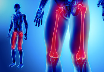
Purpose and Structures Shown Lateral femur and adjacent joints; if needed, use two IRs for demonstration of entire length of adult femur. This position is not usually recommended for patients with fracture or patients who may have destructive disease. There may be a risk of fragment displacement. Patients with these conditions should be examined in supine position.
Position of patient Ask patient to turn onto affected side Adjust body position, and center affected thigh to midline of grid.
Position of part With knee included. For projection of distal femur, draw patient’s uppermost limb forward and support it at hip level on sandbags. Adjust pelvis in true lateral position. Flex affected knee about 45 degrees, place sandbag under ankle, and shift body rotation to place epicondyles perpendicular to tabletop.
Adjust position of Bucky tray so IR projects about 2 inches (5 cm) beyond knee to be included.
With the hip included. For projection of proximal femur, place top of IR at level of ASIS. Draw upper limb posteriorly, and support it. Adjust pelvis so it is rolled posteriorly just enough to prevent superimposition; 10 to 15 degrees from lateral position is sufficient. If shielding, be sure shield doesn’t obstruct area of clinical interest.
Central ray Perpendicular to midfemur and center of IR.
Tib Fib Lateral Mediolateral or Lateromedial

Purpose and Structures Shown Lateral view of entire tibia and fibula.
Position of patient Supine.
Position of part Patient toward affected side with leg on IR. Adjust body’s rotation to place patella perpendicular to IR. Use supports where needed for patient’s comfort and to maintain body position. Lift leg enough for assistant to slide rigid support under patient’s leg. IR may be placed between legs and CR directed from lateral side.
Central ray Perpendicular to IR at midpoint of shin. Include proximal and distal ends of tibia and fibula. If patient must remain supine, the image may be taken cross-table using horizontal CR.
Tib Fib AP Oblique Medial or Lateral Rotations

Purpose and Structures Shown Oblique view of entire tibia and fibula.
Position of patient Supine on radiographic table.
Position of part Perform oblique projections of leg by alternately rotating limb 45 degrees medially or laterally. For medial rotation, ensure that the whole leg is turned inward and not just foot. Place support under greater trochanter if needed.
Central ray Perpendicular to IR at midpoint of shin.
Video Credit : tbailey0312
Video Credit : RadTechEd
RLKA
Read more about this and other subjects and get 2 Category A ARRT® CE Credits in the X-Ray CE Course “Radiography of the Leg, Knee, and Ankle”