Radiographic Positioning Distal Feet

This article discusses radiographic positioning to show the tarsals and distal feet for the Radiologic Technologist (X-Ray Tech).
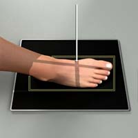
Foot AP Axial
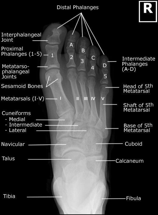
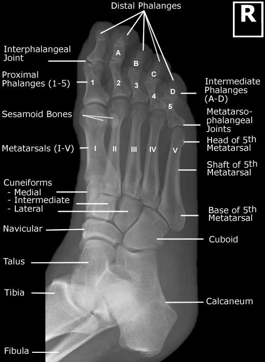
Purpose and Structures Shown Localizing foreign bodies. Determining location of fragments in fractures of metatarsals and anterior tarsals. Talus, metatarsals, and phalanges.
Position of patient Supine position. Knee of affected side flexed, enough to rest sole of foot firmly on IR.
Position of part IR under patient’s foot flat centered on IR. Entire plantar surface rests on IR; take precautions against IR slipping. Ensure that no foot rotation occurs.
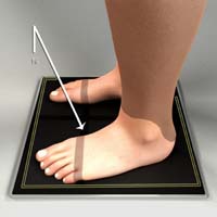
Central ray CR at base of third metatarsal and either 10 degrees toward heel to base of third metatarsal or Perpendicular to IR.
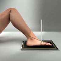
Foot AP Axial (Weight-bearing method – Standing)
Purpose and Structures Shown To get an accurate evaluation and comparison of tarsals and metatarsals. Both feet.
Position of patient Standing upright position.
Position of part IR on floor, patient standing on IR with feet centered on each side. Pull patient’s pants up, if necessary. Place right and left markers and upright marker on IR. Patient’s weight is distributed equally on each foot.
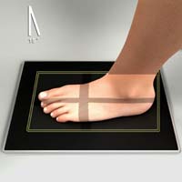
Central ray 10 degrees toward heel is optimal. Minimum of 15 degrees necessary to have enough room to position tube and allow patient to stand. CR pointing between feet and at level of base of third metatarsals.
Foot AP Axial (Weight-bearing Composite)
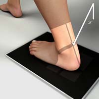
Purpose and Structures Shown Full outline of foot, free of the leg. Bones of the foot.
Position of patient Standing upright position. Patient should attempt carefully maintain position of affected foot, they may need something to lean on.
Position of part Affected foot on top of IR. Have patient place opposite foot one step backward for exposure of forefoot and one step forward for exposure of calcaneus to prevent superimposition of leg shadow.
Central ray For first exposure, tube 15 degrees caudal, CR at base of third metatarsal. For second exposure, anterior angulation of 25 degrees with CR at posterior surface of ankle so that CR emerges on plantar surface at level of lateral malleolus.
Foot AP Oblique (Medial Rotation)
Purpose and Structures Shown To show interspaces between the following: cuboid and calcaneus; cuboid and fourth and fifth metatarsals; cuboid and lateral cuneiform; and talus and navicular bone. A greater rotation can be helpful in demonstrating joint spaces of the foot. Cuboid is shown in profile. Sinus tarsi is also well demonstrated.
Position of patient Supine. Knee of affected side flexed. Plantar surface of foot resting firmly on radiographic table.
Position of part Rotate leg medially until plantar surface of foot forms an angle of 30 degrees to plane of IR. If angle of foot is increased more than 30 degrees, lateral cuneiform tends to be thrown over other cuneiforms.
Central ray Perpendicular to IR at base of third metatarsal.
Foot AP Oblique (Lateral Rotation)
Purpose and Structures Shown Interspaces between first and second metatarsals, medial and intermediate cuneiforms. First and second metatarsals. Medial and intermediate cuneiforms.
Position of patient Supine. Flex knee of affected side enough for plantar surface to rest firmly on table.
Position of part IR under patient’s foot, parallel with its long axis, and center it to midline of foot at level of base of third metatarsal. Rotate leg laterally until plantar surface of foot forms an angle of 30 degrees to IR. Support elevated side of foot on a 30 degrees foam wedge to ensure consistent results.
Central ray Perpendicular to IR at base of third metatarsal.
Foot PA Oblique Grashey Methods (Medial or Lateral Positions)
Purpose and Structures Shown Foot interspaces of the proximal ends of the metatarsals.
Position of patient Prone position. Elevate affected foot on sandbags.
Position of part Adjust elevation of patient’s foot to place its dorsal surface in contact with IR. Position IR under foot, parallel with its long axis; center it to base of third metatarsal. Demonstration of interspaces between first and second metatarsals: rotate heel medially about 30 degrees. Demonstration of interspaces between second and third, third and fourth, and the fourth and fifth metatarsals: adjust foot so heel is rotated laterally about 20 degrees .
Central ray Perpendicular to IR at base of third metatarsal.
Foot PA Oblique (Medial Rotation)
Purpose and Structures Shown Bones of the foot. Articulations between cuboid and adjacent bones (the calcaneus, lateral cuneiform, and fourth and fifth metatarsals). Articulations between talus and navicular bone; navicular bone and cuneiforms; and sustentaculum tali and talus. Cuboid is shown in profile.
Position of patient Lateral recumbent position on affected side. Fully extend leg. Turn patient toward prone position until plantar surface of foot forms an angle of 45 degrees to plane of IR. Flex knees.
Position of part Center IR opposite base of fifth metatarsal, midline should be parallel with long axis of foot. Rest dorsum of foot against a foam wedge. The general survey study – made with the foot at an angle of 45 degrees to obtain uniform results.
Central ray Perpendicular to IR at midline of foot at level of base of fifth metatarsal.
Foot Lateral (Mediolateral)
Purpose and Structures Shown To get clear image of entire foot, ankle joint, and distal ends of tibia and fibula. Entire foot in profile. Ankle joint. Distal ends of tibia and fibula.
Position of patient Lying on effected side.
Position of part Plantar surface of foot perpendicular to IR. Lateral side of foot flat on IR. Dorsiflex foot to form a 90-degree angle with lower leg.
Central ray Perpendicular to IR at the base of third metatarsal.
Foot Lateral (Lateromedial)
Purpose and Structures Shown To demonstrate foot, ankle joint, and distal ends of tibia and fibula.
Position of patient Patient lying on unaffected side.
Position of part Plantar surface of foot perpendicular to IR. Medial side of foot flat on IR. Dorsiflex foot to form a 90-degree angle with lower leg.
Central ray Perpendicular to IR at the base of third metatarsal.
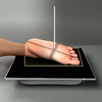
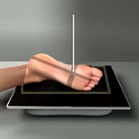
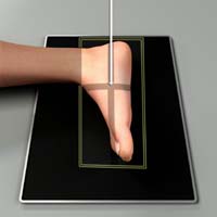
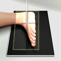
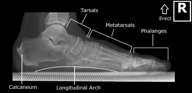
Longitudinal Arch Lateral – Lateromedial (Weight-bearing Standing)
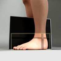
Purpose and Structures Shown To show bones of foot with weight-bearing. Structural status of longitudinal arch. Right and left sides are often examined for comparison.
Position of patient Upright position on a low riser that has an IR groove or using a specialized device for foot x-ray. Patient should have something to help balance.
Position of part IR in the IR groove of stool or between blocks. Patient standing in a natural position, one foot on each side of IR, with weight of body equally distributed on both feet. Adjust IR so that it is centered to base of third metatarsal. After exposure, replace IR and position new one to image the opposite foot. If possible, place a lead shield behind cassette to shield foot from excess exposure.
Central ray Perpendicular to IR at a point just above base of third metatarsal.
Video Credit : klhellens
Read more about this and other subjects and get 2 Category A ARRT® CE Credits in the X-Ray CE Course “Radiography of the Leg, Knee, and Ankle”RLKA