Radiographic Positioning of the Hip and Pelvis

This article discusses radiographic positioning to show the hip and pelvis for the Radiologic Technologist (X-Ray Tech).
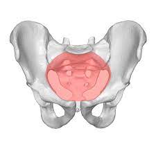
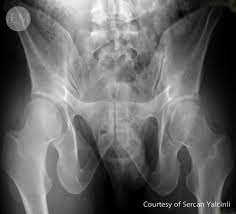
Pelvis AP
Purpose and Structures Shown Clear image of entire pelvis. Also demonstrates head, neck, trochanters, and proximal one third or one fourth of shaft of femur.
Position of patient Supine position. Have patient suspend respiration for exposure.
Position of part

![]()
Unless contraindicated due to trauma or pathologic factors, medially rotate feet and lower limbs about 15 -20 degrees to place femoral necks parallel with plane of the IR. Medial rotation is easier for patient to maintain if knees are supported. Heels should be placed about 8- 10 inches (20 to24cm) apart. Immobilize legs with sandbag across ankles, if needed. Check distance from ASIS to table top on each side to be sure that pelvis is not rotated. Center IR midway between ASIS and pubic symphysis. If pelvis is deep, palpate for iliac crest and adjust position of IR so that its upper border will project 1 to 1.2 inches (2.5to3.8cm) above crest.
Central ray Perpendicular at midline of patient about 2 inches (5cm) inferior to ASIS and 2 inches (5cm) superior to pubic symphysis in average-sized patients.
Video Credit : TheXrayChic
Pelvis Lateral Left or Right

Purpose and Structures Shown Clear image of lateral pelvis. Lumbosacral junction, sacrum, coccyx, superimposed hip bones, and upper femur.
Position of patient Place patient in lateral recumbent, dorsal decubitus, or upright position. Have patient suspend respiration for exposure.
Position of part Recumbent position. When patient can be placed in lateral position, center the midcoronal plane of body to midline of grid. Extend thighs enough to prevent femur from obscuring pubic arch. Place support under lumbar spine, and adjust it to place vertebral column parallel with tabletop. If vertebral column is allowed to sag, it will tilt pelvis in longitudinal plane. Adjust pelvis in true lateral position, with ASIS lying in same vertical plane. Place one knee directly over other knee. A pillow or other support between knees promotes stabilization and patient comfort. Some scholars recommended a dorsal decubitus lateral projection of pelvis for demonstration of “gull-wing sign” in cases of fracture dislocation of acetabularrim and posterior dislocation of femoral head.
Upright position Place patient in lateral position in front of a vertical grid device, and center midcoronal plane of body to midline of grid. Have patient stand straight, with weight of body equally distributed on feet so that midsagittal plane is parallel with plane of IR. If limbs are of unequal length, place support of suitable height under foot of short side. Have patient grasp side of stand for support.
Central ray Perpendicular to a point centered at level of soft tissue depression just above the greater trochanter about 2 inches (5 cm) and to midpoint of image receptor.
Pelvis Axial Chassard-Lapine Method

Purpose and Structures Shown For measuring horizontal, or bi-ischial diameter in pelvimetry. To determine relationship of femoral head to acetabulum. To demonstrate opacified rectosigmoid portion of colon.
Shows the axial projection of pelvis and the relationship between femoral heads and acetabula, pelvic bones, and any opacified structure within pelvis.
Position of patient Seat patient well back on end or side of table so posterior surface of knee is in contact with edge of table. Have patient suspend respiration for exposure.
Position of part If patient is seated at side of table, place longitudinal axis of IR perpendicular to midsagittal plane. If patient is seated on end of table, center midsagittal plane of body to midline of grid. If needed, place a stool or other suitable support under feet.
To prevent thighs from limiting flexion of body too greatly, have patient abduct them as far as end of table permits. Instruct patient to lean directly forward until pubic symphysis is in close contact with table; vertical axis of pelvis will be tilted forward about 45 degrees. Average patient can achieve this degree of flexion without strain. Have patient grasp ankles to aid in maintaining position.
Central ray Perpendicular through lumbosacral region at level of greater trochanters.
When flexion of body is restricted, direct CR anteriorly, perpendicular to coronal plane of pubic symphysis.
Hip AP Oblique Bilateral

Purpose and Structures Shown Pelvis, femoral neck without superimposition, and lesser trochanter on medial side of femur.
Position of patient Supine. Have patient suspend respiration for exposure.
Position of part Adjust body to center ASIS of affected side to midline of grid.
Have patient flex hip and knee of affected side and draw foot up to opposite knee as much as possible.
After adjusting perpendicular CR and positioning IR tray, have patient brace sole of foot against the opposite knee and abduct thigh laterally about 45 degrees. Pelvis may rotate slightly.
Central ray Perpendicular at midsagittal plane 1 inch (2.5cm) superior to pubic symphysis. For unilateral position, direct CR to femoral neck.
Hip AP Oblique Modified Cleaves Method Bilateral

Purpose and Structures Shown Pelvis, femoral neck without superimposition, and lesser trochanter on medial side of femur.
Position of patient Supine. Have patient suspend respiration for exposure.
Position of part Pelvis not rotated. This can be achieved by placing two ASISs equidistant from table.
Place compression band across patient well above hip joints for stability, if needed.
Have patient flex hips and knees and draw feet up as much as possible and hold this position.
Abduct thighs as much as possible, and turn feet inward to brace soles against each other for support. Angle may vary between 25 and45 degrees depending on how vertical femur can be placed.
Center feet to midline of grid. If possible, abduct thighs about 45 degrees from vertical plane to place long axes of femoral necks parallel with plane of IR. Check position of thighs, being careful to abduct them to same degree.
Central ray Perpendicular at midsagittal plane 1 inch (2.5cm) superior to pubic symphysis.
Hip AP

Purpose and Structures Shown Femoral head, neck and proximal 1/3 of body of femur, regions of ilium and pubic bones adjoining pubic symphysis, hip joint, and greater trochanter profile.
For initial examination of hip lesion, AP projection is often obtained using an image receptor large enough to include entire pelvic girdle and upper femur.
Trauma patients with severe injury are not usually transferred to table but are radiographed in stretcher or bed. Any limb manipulation on trauma patients should be done by a physician.
Position of patient Supine. Have patient suspend respiration for exposure.
Position of part Pelvis not rotated. This can be achieved by placing two ASISs equidistant from table.
Medially rotate lower leg and foot about 15-20 degrees to place femoral neck parallel with plane of IR, unless this maneuver is contraindicated or other instructions are given.
Central ray Perpendicular to femoral neck. Place CR about 2 1/2 inches (6.4cm) distal on a line drawn perpendicular to midpoint of line between ASIS and pubic symphysis. Make any necessary adjustments if an orthopedic implant is to be shown.
Hip Lateral Mediolateral

Purpose and Structures Shown Hip joint, acetabulum, femoral head and relationship of femoral head to acetabulum.
Position of patient From supine position, rotate patient slightly toward affected side to oblique position. Degree of obliquity will depend on how much patient can abduct leg. Have patient suspend respiration for exposure.
Position of part Adjust patient’s body, and center affected hip to midline of grid. Ask patient to flex affected knee and draw thigh up to position at nearly a right angle to hipbone. Keep body of affected femur parallel to table. Extend opposite limb and support it at hip level and under knee. Rotate pelvis no more than necessary to accommodate flexion of thigh and avoid superimposition of affected side.
Central ray Perpendicular through hip joint, located midway between ASIS and pubic symphysis for Lauenstein method and at a cephalic angle of 20-25 degrees for Hickey method.
Hip Lateral Mediolateral (Dunn View)


Purpose and Structures Shown Hip joint, acetabulum, femoral head and relationship of femoral head to acetabulum. To examine the femoral anteversion, an oblique lateral radiograph of the femur, this view is frequently performed by orthopedists in a position of only 70° instead of 90° flexion and about 50° of abduction.
Position of patient For this, a Dr. named Dunn developed a positioning apparatus, although the view can also be done without the device. In small children both hips are depicted on one film. In adults, separate axial views of each hip are taken. The legs are flexed exactly 90° at the hips and knees. The lower legs are parallel to the sides of the table to eliminate any medial or lateral rotation of the hip and the thighs. They are perpendicular to the table. The hips are abducted 20°.
Position of part Adjust patient’s body, and center affected hip to midline of grid. Ask patient to flex affected knee and draw thigh up to position at nearly a right angle to hipbone. Keep body of affected femur parallel to table. Extend opposite limb and support it at hip level and under knee. Rotate pelvis no more than necessary to accommodate flexion of thigh and avoid superimposition of affected side.
Central ray Perpendicular through hip joint, located midway between ASIS and pubic symphysis for the single view, and at the symphesis pubis for the bilateral view.
Hip Axiolateral Danelius-Miller Method

Purpose and Structures Shown Femoral head, neck, and trochanters of femur, hip joint with acetabulum, ischial tuberosity below femoral head, any orthopedic appliance in its entirety.
Position of patient Supine. Have patient suspend respiration for exposure.
Position of part Raise pelvis as needed to center most prominent point of greater trochanter to midline of IR.
Flex knee and hip of unaffected side to elevate thigh in vertical position. Rest unaffected leg on suitable support that will not interfere with CR. Shift pelvis so it is not rotated. Unless contraindicated, grasp heel and medially rotate foot and lower limb of affected side about 15-20 degrees. Manipulation of patients with unhealed fractures should be done by a physician.
Central ray Perpendicular to long axis of femoral neck. CR enters mid-thigh and passes through femoral neck. Cassette propped up to be perpendicular to CR.
Hip Axiolateral Clements-Nakayama Modification

Purpose and Structures Shown Hip joint with acetabulum, femoral head, neck, trochanters in lateral profile.
Lateral hip image, CR is angled 15 degrees posterior instead of toes being medially rotated.
Position of patient Supine on table with affected side near edge of table. Have patient suspend respiration for exposure.
Position of part Rotate limb internally. Limb remains in a neutral or slightly externally rotated position. Support IR so its lower margin is below patient.
Central ray Directed 15 degrees posteriorly and aligned perpendicular to femoral neck. Cassette propped up parallel to axis of femoral neck and tilt its top back 15 degrees.
Video Credit : Dennis Bowman
Hip Axiolateral Friedman Method

Purpose and Structures Shown Femoral head, neck, trochanters, and shaft.
Position of patient Lateral recumbent on affected side. Center midcoronal plane of body to midline of table. Have patient suspend respiration for exposure.
Position of part Extend affected leg in lateral position bending knee slightly.
Central ray Directed to femoral neck at an angle of 35 degrees cephalad. Optionally CR may be angled 15 or 20 degrees cephalad for this position.
Hip PA – Oblique Hsieh Method

Purpose and Structures Shown To demonstrate posterior dislocations of femoral head in cases other than acute fracture dislocations. Clearly shows ilium, hip joint, and proximal femur.
Position of patient Semi prone position. Have patient suspend respiration for exposure.
Position of part Elevate unaffected side about 40-45 degrees and have patient support body on flexed knee and forearm of elevated side. Adjust position of body to place posterior surface of affected iliac bone over midline of grid.
Central ray Perpendicular passing between posterior surface of the iliac blade and dislocated femoral head.
Hip Mediolateral Oblique Lilienfeld Method

Purpose and Structures Shown Hip joint, femoral head, acetabulum, and ilium.
Position of patient Lateral recumbent position on affected side. Have patient suspend respiration for exposure.
Position of part Fully extend affected thigh, adjust it in a true lateral position, and immobilize it. Roll upper side gently forward about 15 degrees or just enough to separate two sides of pelvis. Support limb at hip level.
Gently roll the upper hip forward, affected hip will not change position; pelvis will rotate from femoral head.
Central ray Perpendicular to midpoint of IR, traversing affected hip joint at level of greater trochanter.
Hip Acetabulum PA Axial Oblique Teufel Method

Purpose and Structures Shown Hip joint and acetabulum, femoral head in profile to show concave are of fovea capitis.
Position of patient Semi prone position on affected side. Have patient suspend respiration for exposure.
Position of part Align body, and center hip being examined to midline of grid. Elevate unaffected side so that the anterior surface of the body forms a 38 degree angle from table. Have patient support body on forearm and flexed knee of elevated side.
Central ray Directed through acetabulum at an angle of 12 degrees cephalad. CR enters body at inferior level of coccyx and about 2 inches (5cm) lateral to midsagittal plane toward side being examined.
Hip Acetabulum RPO or LPO – Judet Method

Purpose and Structures Shown Acetabular rim.
Position of patient Internal Oblique – Place patient in a semi supine position with affected hip up. External Oblique – Place patient in a semi supine position with affected hip down. Have patient suspend respiration for exposure.
Position of part Align body, and center hip being examined to middle of IR. Raise affected side so that anterior surface of body forms a 45 degree angle from table.
Central ray Internal Oblique – Perpendicular to IR and entering 2 inches inferior to ASIS of affected side. External Oblique – Perpendicular to IR and entering at pubic symphysis.
Pelvic Bones PA

Purpose and Structures Shown Pubic and ischial bones, hip joint, symmetric obturator foramina.
Position of patient Prone position Have patient suspend respiration for exposure.
Position of part Center at level of greater trochanters.
Central ray Perpendicular at distal coccyx and exits pubic symphysis.
Pelvic Bones AP Axial “Outlet” Taylor Method

Purpose and Structures Shown Pubic and ischial bones, symmetric obturator foramina, hip joints.
Shows the rami without foreshortening seen in a PA or AP projection (due to the CR more perpendicular to the rami.
Position of patient Supine. Have patient suspend respiration for exposure.
Position of part Center midsagittal plane of patient’s body to midline of grid. Adjust pelvis so it is not rotated. ASISs should be equidistant from the table.
Central ray Males – Directed 20 to 35 degrees cephalad and centered to a point 2 inches (5cm) distal to the superior border of the pubic symphysis. Females – Directed 30 to 45 degrees cephalad and centered to a point 2inches (5cm) distal to the upper border of pubic symphysis.
Pelvic Bones Superoinferior Axial Inlet Lilienfeld Method

Purpose and Structures Shown Anterior pelvic bones, hip joints, superoinferior axial projection of anterior pubic and ischial bones and pubic symphysis. The “Inlet” can also be demonstrated with patient supine and CR angled 40 degrees caudad.
Position of patient Seated upright in table, leaning back. Extend arms for support, lean backward 45 or 50 degrees, arch back, if possible, to place pubic arch in a vertical position. Have patient suspend respiration for exposure.
Position of part Flex knees slightly and support them to relieve strain. Adjust pelvis so that ASIS are equidistant from table.
Central ray Perpendicular at level of greater trochanters centered on mid sagittal plane.
Pelvic Bones PA Axial Inlet Staunig Method
Purpose and Structures Shown Medially superimposed superior and inferior rami of pubic bones, symmetric pubes and Ischia, pubic and ischial bones centered to radiograph, hip joints.
Position of patient Prone Have patient suspend respiration for exposure.
Position of part Adjust the body so that pelvis is not rotated.
Central ray Directed 35 degrees cephalad exiting the pubic symphysis on the midsagittal plane anteriorly at level of greater trochanters.
Alternative AP Inlet and Outlet Views
Pelvis Intel
Pelvis Outlet
Pelvic Bones Ilium PA Oblique Projections

Purpose and Structures Shown Entire ilium, hip joint, proximal femur (femoral head within acetabulum), sacroiliac joint. Also shows unobstructed projection of sciatic notches and a profile image of acetabulum.
PA oblique projection of ilium in profile.
Position of patient RAO and LAO – Prone. Have patient suspend respiration for exposure.
Position of part Elevate unaffected side about 40degrees to place affected ilium perpendicular to plane of IR. Have patient rest on the forearm and flexed knee of elevated side. Adjust position of uppermost thigh to place iliac crests in same horizontal plane.
Central ray Perpendicular to midpoint of IR at level of ASIS.
Pelvic Bones Ilium AP Oblique Projections

Purpose and Structures Shown Entire ilium, hip joint, proximal femur (femoral head within acetabulum), sacroiliac joint. Also shows unobstructed projection of sciatic notches and a profile image of acetabulum. AP oblique projection of broad surface of iliac wing without rotation.
Position of patient RPO and LPO – Supine. Have patient suspend respiration for exposure.
Position of part Elevate unaffected side about 40 degrees to place broad surface of wing of affected ilium parallel with plane of IR. Support elevated shoulder, hip, and knee on sandbags. Adjust position of uppermost limb to place ASISs in the same transverse plane.
Central ray Perpendicular to midpoint of IR at level of ASIS.
RPAH
Read more about this and other subjects and get 1 Category A ARRT® CE Credit in the X-Ray CE Course “Radiography of the Hip and Pelvis”
Visit here to know more about femur labeled and hip x-ray positioning.